|
|
|
Universal Serial Bus (USB)
Thomas D. Haney
University of Central Florida
Dr. Janusz Zalewski
June 25, 2001
Table of Contents:
I. Introduction
II. Problem Description
III. Design Solution
IV. Examples
V. Conclusion
VI. Literature List
I. Introduction:
Since the 1980�s the growth of personal computer sales has increased dramatically, and the Internet has entered many areas of the world. At the millennium, the computers clock speed topped the 1GHz level, and computers have been designed for performance. The standard user has many different needs at the local and network levels. At the local level, these needs include numerous peripheral devices like scanners, cameras, printers, keyboards, mice, and joysticks. With each of these devices there are a couple different means for installation on an operating system, and several different means of connectivity. At the network level, the needs of the users have changed to include home networking, Internet access, and the use of community local area networks. The networking uses have many different installation techniques and mediums, too. The existing hardware included the serial based interfaces and the serial bus ( [3], pp 1). The devices that used this interface had to be mapped directly to the CPU's input and output addresses.
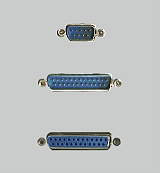
Figure 1-1. Existing parallel and serial ports.
Also, these peripherals were assigned IRQs and at times DMA channels ( [1], pp11). Since there are a limited number of IRQ address, this would present problems as devices were added to an existing system. The software for these devices had to be designed with a specific data packet in mind. The term "legacy device" defines a device that is not Plug N' Play. Some of these devices may have physical settings (DIP switches or jumpers) or do not have the ability to communicate with a Plug N' Play operating system for automatic configuration. These devices are part of the (ISA) Industry Standard Architecture and were often difficult to setup by the IRQ and DMA settings. Each of these mediums had different data packets and windows drivers. Due to the complex configurations and numerous types of interfaces, the developers of peripheral devices and the common PC user were faced with a great deal of frustration ( [1], pp 11). The existing mediums were too different and there was not one type of existing interface that would support all applications. Also, the interfaces and buses were separate, and the ports did not support the means for easy upgrade. Bandwidth on the bus was also an issue for some devices. Some peripherals take bandwidth "as available" witch are called asynchronous bandwidth, and others need "guaranteed" bandwidth witch is called isynchronous bandwidth ( [3], pp13). When a system is overloaded by too much demand for bandwidth, it can be very unstable or not function. Stability and functionality are necessary to a computer user, and a system would need to be put in to place to account for this availability of bandwidth on a bus. The complexity, bandwidth, and standardization issues were causing a problem.
II. Problem Description:
The need for numerous peripheral devices, Internet, and Networking connectivity products creates issues for available ports, speed, and ease of installation for the common user. In previous years, when a new local device was purchased, the user had to know about available ports, operating system, clock speed, RAM, and had to have the knowledge to install the device. When the peripheral device required a port that was unavailable, the user had to buy expansion cards, have an available bay, install the expansion port physically, and then install the device in the operating system before even starting with the new peripheral. The parallel port has BIOS settings to switch the modes of the port from standard, bi-directional, and ECP/EPP, and this process can cause problems for the users too. This process needed simplification for the common home computing user. The common user had to have a better means for using the Plug N� Play system. This Plug N� Play system had to do more than detecting the port and device, but also allowing the software and operating system to set the mode of operation.
Users in the past had to know about their system's interrupts, input/output memory addresses, shared and non-shared interfaces, types of expansion cards, available ports, and types of cables to use with the ports to properly configure their system ( [1], pp12-16). Aside from the complexity and knowledge, the users are faced with the cost of upgrading the PC to add peripherals. Device manufacturers would need to simplify the process, reduce the cost, and integrate the interfaces to make the development and usage of peripheral easier. Some of the ideas for upgrading the current conventions included standardizing the connection, ability to attach many devices to a single connection, changing the system's use of interrupts and DMA to prevent conflicting devices, and automatic detection of devices and configurations ( [1], pp17). There were needs and demands to lower the cost, enhance the capability of performance, and lower the power consumption ( [1], pp18). They also wanted to provide a new type of support that would easily configure to future computer developments, support the use of legacy hardware/software, enhance the "plug n' play" devices, support real-time devices, and bus powered devices ( [1], pp18/ [3], pp12).
To further discuss these ideas, we will look a bit closer at them. To lower the cost to the developers and consumers, a standardized low- to mid-speed interface had to be created. This would allow manufacturers and developers to support and design around single medium. Also, the cost to the customer would be reduced, and this would make devices and PC components more affordable. Enhancing the performance is always the demand of the PC user. The existing serial interface and bus supported about a 56 kilobytes/second data transfer rate.( [3], pp15). To make a standard a broader and flexible rate would be needed. The low speed devices would include your keyboard and mouse and other interactive input/output devices that were using 10 to 100 kilobytes/second. And, the mid speed applications for multimedia devices like printers, scanners, and other external devices were supporting 500 kilobytes/second to 10 megabits/second ( [1], pp20). The solution device would need to be one that can support many low- to mid-speed applications, and leave room for product enhancement. Power consumption is always a modification that needs to be considered. By delivering the power to most peripheral devices and powering the signal, the interface and bus consume power. With the growing concern of power conservation, like Energy Star products and the usage of suspend/sleep modes, the system would not want to consume power when it is not being used. In reference to all of the wanted support on the new interface, an integration between software configuration and hardware would need to occur. The existing hardware mediums were presenting too much complexity during the software configuration. A new system was needed to replace the existing mediums, and would need to allow the software to auto configure and support the bus usage.
III. Design Solution:
The structure:
The solution to the problem was a universal connection that would have access directly to a serial bus, thus producing the name Universal Serial Bus. There had to be a structure designed for the USB to peripheral interface for software, and a USB to bus interface on the hardware. This new medium could automatically configure Plug N' Play devices or give standard options for the use of legacy devices. The solution for USB can better be described with graphics. (Graphics based on [1], pp 28, 30 and [2], pp2)
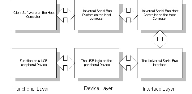
Figure 3-1. The software layers.
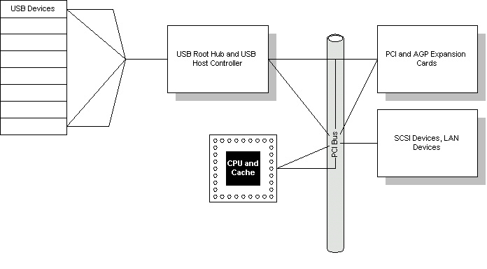
Figure 3-2. The hardware bus interface.
The hardware connectivity produced a "window" directly into the Peripheral Component Interconnect (PCI) Bus that would support 12 MB/s data transfer rates ( [3], pp2, 25). With this connection (Fig 3-2), the USB root hub and controller can configure devices and dynamically allocate bandwidth when a device is connected. Also, a generic peripheral interface can be implemented to simplify the design and configuration procedures. Also, this is the port and cable structure that was agreed upon.
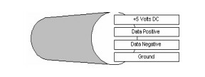
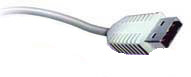
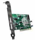
Figure 3-3. The internal design of the cable. Figure 3-4. The cable. Figure 3-5. The USB PC port.
The communication:
With the hardware listed above, a communication system had to be standardized. There are two connections within the USB connection for power (Figure 3-3). These are rated at 30V AC (rms) and can support 1A maximum per contact at 30 degrees Celsius. It also will support a 0-40 degree Celsius operating environment. The other two cables, data positive and negative (Figure 3-3), can be used several different ways by the system. In the following paragraph is paraphrased from the "USB Handbook" ( [2], pp6-7), and contains the four USB transfer types.
The first type on transfer, that can be used over a USB cable, is for control. It consists mostly for setup data transfers and changes in peripheral status. This is a host to device transaction that is transmitted full speed in 8-64 byte packets, or 8 byte for low-speed applications. This transfer type will return busy status during some stages, until complete. This types usage can only accept the data or fail to return a handshake (if data is deemed corrupt). The second type of transfer is isynchronous, and is used for unidirectional communication. At full speed, the transmission has guaranteed bandwidth with a maximum of 1023 bytes per frame. This type does not allow for handshakes (unidirectional), and will not retransmit if failure occurs. Another type of transfer is the interrupt transmission. This allows for input only, and is nearly the unidirectional reverse of control. The transmission speed is the same at maximum and minimum, but can not exceed the maximum service interval. This maximum interval is 1-255 milliseconds at full speed, and 10-255 milliseconds at low speed. Because it is designed for peripheral input only, handshakes are not made. Although a developer can have embedded toggling sequences for data transmissions, there is not a guarantee that the information is received if stalling occurs. The final transmission type is the bi-directional bulk transfer. This method operates at full speed only in 8-64 bytes/frame packets. There is a toggle that occurs on every handshake for successful data transfer. This method is configured for stalling conditions, and will reset itself.
The Packets:
The following paragraph is a deeper look at the packets, by the "USB Handbook" ( [2], pp9)
The control packet is made up of a setup transaction, multiple IN and OUT data transactions, and followed up by a status transaction.
SETUP------One or more bi-directional DATA-------STATUS.
The isynchronous packet consists of one or more data transactions. They can be either all IN or all OUT.
DATA----DATA----DATA (All in the same direction)
The interrupt transmission has a packet that consists of one or more IN data transmissions.
IN DATA----IN DATA---IN DATA
The bulk transmission consists of one or more IN or OUT data transmissions.
DATA-----DATA-----DATA (Bi-Directional)
Information added at the request of Dr. Zalewski:
For the SETUP, IN, and OUT there is a 7-bit address, 4-bit endpoint, and a 5-bit CRC. The root hub can support 128 devices because of the 7-bit address (0000000 to 1111111). The address determines the USB device that is to accept the transmission. This is necessary to configure the root hub properly. The 5-bit CRC is a Cyclic Redundancy Check. This transmission must be received properly for the data to be accepted. The sequence of data that is transmitted to the USB device is as follows:
SETUP, IN, OUT, or other value.
7-bit Address for destination device
4-bit Endpoint value
5-bit CRC value for determining data consistency
Data 0 or Data 1 (alternating)
CRC16 signal (end of data)
Acknowledge signal if necessary by transmission type.
The table below indicates the codes that are transmitted in the packet to determine the use for the data.
|
Value |
Type |
Category |
More Information |
|
0101 |
SOF |
TOKEN |
Every 1 millisecond |
|
1101 |
SETUP |
TOKEN |
Setup does not receive an ACK |
|
1001 |
IN |
TOKEN |
Configuration |
|
0001 |
OUT |
TOKEN |
Configuration |
|
0011 |
Data 0 |
Data |
Data alternates between Data 0 and Data 1. |
|
1011 |
Data 1 |
Data |
Same as above |
|
0010 |
ACK |
Handshake |
Transmits to acknowledge successful data transfers |
|
1010 |
NAK |
Handshake |
System is busy or does not have the resources |
|
1110 |
STALL |
Handshake |
Help from system |
The drivers' roles:
The USB device's driver initiates a transfer by a Input/Output Request Packet (IRPs) ([3], pp30). This packet is sent to the USB Host Controller for the computer system. The Host Controller driver (HCD) also schedules the transactions by building a sequenced "frame list" ( [1], pp31) These transactions are then sent to the USB Root Hub which provides the appropriate attachment between the system and device ( [1], pp32).
Reading Vs. Writing to a USB device:
This functionality is described best by "Universal Serial Bus Architecture" by Anderson. The following is a paraphrased description of the read and write operations ( [2], pp32):
The Host controller performs both tasks writing and reading. For writing to a target device, the host controller will first need to allocate some memory to the target device. Then, the host controller performs a parallel to serial conversion on the data. This is due to the design of the connection, and the positive and negative data lines. Once complete, the transaction is passed to the root hub for connection and broadcasting. For reading a device, the root hub automatically send the transaction to the root hub for connection. The root hub broadcasts the data through the bus to all devices. The specified device recognizes the command, and acknowledges the need for data. The data is passed through the root hub to the host controller. The host controller must convert the data, like in the write operation using a buffer, and then send it back to the root hub to go to the device again. The root hub and devices perform regular checks for data consistency, and when errors are reported, the host controller will be told of a problem to output to running software.
IV. Examples:
From the user's point of view, a typical software installation for a USB device are as follows. For Macintosh OS 8.6-X, it is assumed you are using USB. As long as the proper extensions are listed in your extension manager, the device will not even prompt for your port settings. However, for IBM compatibles using Microsoft Windows 95 (version B)-Windows XP, or Windows 2000 professional/server there are a couple more steps. The USB hub determines the upstream or downstream by basic switching. When a device is connected (powered on if applicable by an external power supply), the USB controller will need to have configuration settings for the device. Here is a link to a typical installation. Assuming that it has not been installed before, no operating system drivers will be available for the controller, then a Windows based wizard will open to get the drivers and configure the controller for the device. Once installed through the wizard, the client based software will also need to be loaded. This software actually sets the data transfer methods and events. Here is a link to a typical USB peripheral installation. This is a lot easier than configuration of ports, installing hardware, needing to know IRQ and DMA settings on your system, and having to reboot every time a connection is added to the system.
From the developers point of view, they now know that the user will have the proper communication and settings, because they will be determined by software. There is a bit more planning involved with designing a USB Windows based driver. This would require a bit of work for peripherals that were using port based settings. Now the designers would need to write Windows based drivers aside from just writing the port in the programs source code. This driver will provide the identification and communication that the peripheral device will require.
|
In the [DRIVER.DRV] section, the following entry ensures that the
Microsoft-provided USB port monitor is installed under Windows 98: PortMonitor=usbmon.dll,usbmon.dll In the [MONITOR] section, the following entry instructs Setup not to copy this file if it already exists on the system: usbmon.dll,,,16 This entry uses the COPYFLG_NO_OVERWRITE flag (hexadecimal 10) to instruct Setup not to copy this file if it already exists on the system. This causes Setup to install Usbmon.dll on Windows98 and Windows98 SE but not on Windows Me. Usbmon.dll on Windows Me is a system-protected file and is already present, so this file does not need to be installed by a driver package. [Version] Signature="$CHICAGO$" Class=Printer ClassGUID={4d36e979-e325-11ce-bfc1-08002be10318} Provider=%MS% CatalogFile=print9x.cat CatalogFile.NT=print2K.cat DriverVer=1/1/2000,4.00.2450.1 ; The Manufacturer section lists all of the manufacturers that we will ; display in the Dialog box [Manufacturer] "Man" [HP] "Man printer" = DRIVER.DRV,MYPNPID [DRIVER.DRV.NT] ; Windows 2000 printer driver installation entries go here. [DRIVER.DRV] ; Windows 95/98/Me printer driver installation entries go here. CopyFiles=@DRIVER.DRV,UNICLR,FINSTALL,MONITOR DataSection=UNI_DATA PortMonitor=usbmon.dll,usbmon.dll DriverVer=1/1/2000,4.00.2450.1 [MONITOR] usbmon.dll,,,16 [FINSTALL] finstall.dll finstall.hlp [UNICLR] iconlib.dll dmcolor.dll unidrv.dll unidrv.hlp [UNI_DATA] HelpFile=unidrv.hlp DefaultDataType=EMF [DestinationDirs.NT] DefaultDestDir=66000 [DestinationDirs] DefaultDestDir=11 [SourceDisksNames.NT] 2 = %Disk2%,,,"" [SourceDisksNames] 1 = %Disk1%,,,"" [SourceDisksFiles.NT] ;NT files to install [SourceDisksFiles] printer.inf = 1 finstall.dll = 1 finstall.hlp = 1 driver.drv = 1 iconlib.dll = 1 dmcolor.dll = 1 unidrv.dll = 1 unidrv.hlp = 1 usbmon.dll = 1 [Strings] MS="Microsoft" Disk1="Win9x disk" Disk2="Win2000 disk" |
Conclusion:
In regards to the problem, the Universal Serial Bus took over the burden of many devices. This role on a computer system is always in demand and need for modifications. The installation is a lot easier for the common PC user. The cost of a USB connection is very comparable to a parallel connection, but the "cable craziness" is out of the picture and interchangeability is much more valuable. The device drivers can be written to store the configurations for a device, and the need for "thick" configuration manuals is depleting. The computer does not need to be rebooted when removing and swapping devices occurs, unless it has not been installed. The support for a better "plug n' play" and for older legacy devices has been implemented into the software. The USB initiates a suspend on after no activity on the bus for 3 milliseconds, reducing power consumption of peripherals to no more than 500 micro-Amps ( [1], pp23). The USB interface has been upgraded already to accommodate higher speed devices. With the boom of audio/video devices for the home PC, the need for faster steaming has added a second revision to USB. USB 2.0 achieves better speeds by the use of a 40X multiplier, and is estimated electrically to be able to support 480 Mbps (USB-IF USB20.pdf). The USB connection will be a part of computer for at least a few more years. Most major manufactures have eliminated parallel connections and added USB ports. These manufactures include Dell, Gateway, and Compaq. There are many communication issues that can be experienced when updated drivers are needed. With the need for device, USB controller, and Windows drivers the user now experiences more software based conflicts. The software is now all that needs to be revised when making a device or fixing a problem.
VI. Literature List:
[1] Anderson, Don. "Universal Serial Bus System Architecture". Mindshare Inc., Massachusetts,1997.
[2] Jaff, Kosar "Universal Serial Bus Handbook". Annabooks, San Diego, November 1996.
[3] McDowell, Steven and Seyer, Martin D. "USB Explained". Prentice Hall, New Jersey, 1999.
Other visited information:
Intel Corporation datasheets, specifications, and schematics. http://www.intel.com/design/usb/
Microsoft Corporation white papers, driver examples, and specifications. http://www.microsoft.com/hwdev/usb/#Papers
Nortel Networks Corp. documentation on broadband USB modems. http://www.nortelnetworks.com/products/library/collateral/56296.02-11-00.pdf http://www.nortelnetworks.com/products/library/collateral/56004.39-04-00.pdf
USB Implementers Forum, Inc FAQ. http://www.usb.org/faq.html
USB Central links for detailed information.. http://www.lvr.com/usb.htm